
HN-1851ATG Direct-Mount Flanged Pressure Transmitter
HONZEN INSTRUMENTS · HN-1851ATG
HN-1851ATG Direct-Mount Flanged Pressure Transmitter
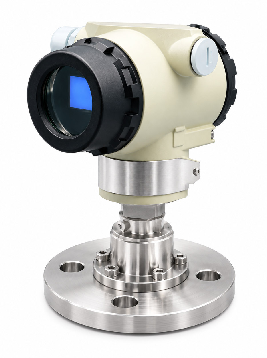
The HN-1851ATG provides direct flange-mounted pressure measurement, with flange standard and size selected for the installation.
Overview
The HN-1851ATG provides direct flange-mounted pressure measurement, with flange standard and size selected for the installation.
Key Features
- Monocrystalline silicon sensor with static-pressure and temperature compensation.
- Two-wire 4–20 mA DC + HART output.
- Local three-button and remote configuration; LCD is listed as an ordering option.
- Choice of isolating diaphragm materials.
Technical Specifications
| Parameter | Catalogue value |
|---|---|
| Measured media | Liquids, gases and steam |
| Output signal | 4–20 mA DC + HART, two-wire |
| Power supply | 10.5–45 V DC, general purpose; 10.5–26 V DC, intrinsically safe |
| Allowable load | 0–600 Ω at 24 V DC |
| Ingress protection | IP66 |
| Isolating diaphragm options | SUS316L, Hastelloy C-276, tantalum, gold-plated |
| Process connection | Flange standard A–J, size 01–05 and material 06–08; see ordering table below |
Measuring range
| Sensor code | Measuring range | Maximum working pressure |
|---|---|---|
| M1 | 0 to 40 kPa | 25 MPa |
| M2 | 0 to 100 kPa | 25 MPa |
| M3 | 0 to 400 kPa | 25 MPa |
| L1 | 0 to 4 MPa | 40 MPa |
| L2 | 0 to 40 MPa | 40 MPa |
| L3 | 0 to 60 MPa | 40 MPa |
Some combinations of measuring range and maximum working pressure printed in the source require confirmation before ordering.
Applications
For the corresponding pressure, differential-pressure or level duties in petroleum, petrochemical, chemical and power applications. Confirm the medium and installation conditions for each selection.
Dimensions
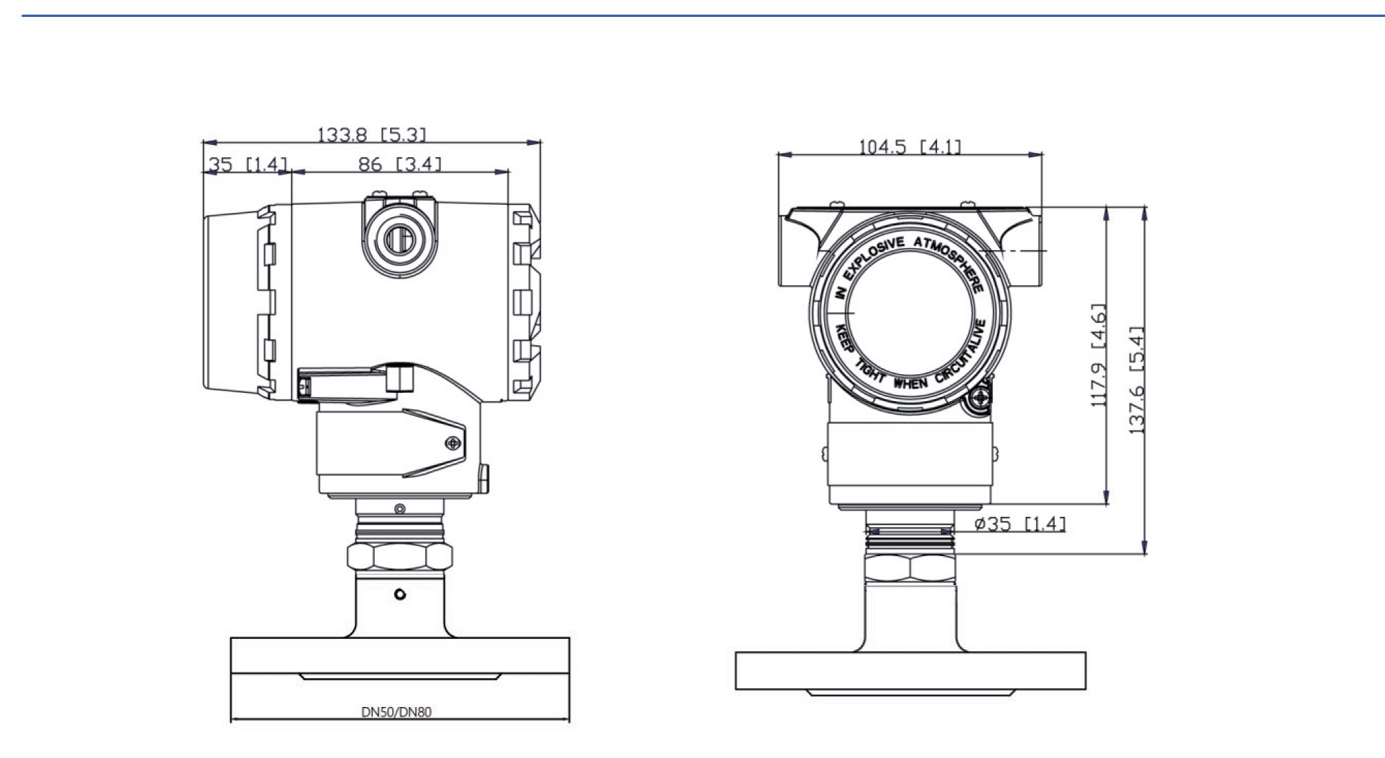
Dimensions and units are as marked on the technical drawings below.
Model Selection / Ordering Information
| Item | Code | Description |
|---|---|---|
| Output | H | 4–20 mA + HART digital communication |
| Sensor code | M1 | 0 to 40 kPa; 25 MPa |
| Sensor code | M2 | 0 to 100 kPa; 25 MPa |
| Sensor code | M3 | 0 to 400 kPa; 25 MPa |
| Sensor code | L1 | 0 to 4 MPa; 40 MPa |
| Sensor code | L2 | 0 to 40 MPa; 40 MPa |
| Sensor code | L3 | 0 to 60 MPa; 40 MPa |
| Isolating diaphragm options | SS | SUS316L |
| Isolating diaphragm options | HC | Hastelloy C-276 |
| Isolating diaphragm options | TA | tantalum |
| Isolating diaphragm options | GD | gold-plated |
| Flange standard | A | ANSI 150 · 2 MPa |
| Flange standard | B | ANSI 300 · 5 MPa |
| Flange standard | C | ANSI 600 · 11 MPa |
| Flange standard | D | ANSI 900 · 15 MPa |
| Flange standard | E | ANSI 1500 · 26 MPa |
| Flange standard | F | DIN PN 10/16 · 1.6 MPa |
| Flange standard | G | DIN PN 25/40 · 4 MPa |
| Flange standard | H | DIN PN 64 · 6.4 MPa |
| Flange standard | I | DIN PN 100 · 10 MPa |
| Flange standard | J | DIN PN 160 · 16 MPa |
| Flange size | 01 | DN25 |
| Flange size | 02 | DN50 |
| Flange size | 03 | DN65 |
| Flange size | 04 | DN80 |
| Flange size | 05 | DN100 |
| Flange material | 06 | SUS304 |
| Flange material | 07 | SUS316 |
| Flange material | 08 | Other requirements |
Catalogue ordering example: HN-1851ATG-H-M1-SS-A-01-06-01-D
Request a Quote
Please provide the process medium, measuring span, process pressure, temperature, wetted material, connection and hazardous-area requirements for selection review.
Technical data from Pressure and Differential Pressure Transmitters catalogue, PDF pages 32–35.